
Page 276 - Complete Wireless Design
P. 276
Filter Design
Filter Design 275
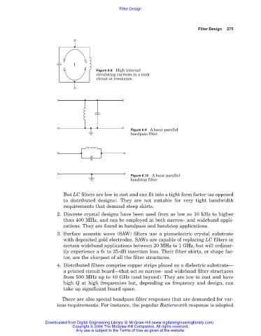
Figure 6.8 High internal
circulating currents in a tank
circuit at resonance.
Figure 6.9 A basic parallel
bandpass filter.
Figure 6.10 A basic parallel
bandstop filter.
But LC filters are low in cost and can fit into a tight form factor (as opposed
to distributed designs). They are not suitable for very tight bandwidth
requirements that demand steep skirts.
2. Discrete crystal designs have been used from as low as 10 kHz to higher
than 400 MHz, and can be employed in both narrow- and wideband appli-
cations. They are found in bandpass and bandstop applications.
3. Surface acoustic wave (SAW) filters use a piezoelectric crystal substrate
with deposited gold electrodes. SAWs are capable of replacing LC filters in
certain wideband applications between 20 MHz to 1 GHz, but will ordinar-
ily experience a 6- to 25-dB insertion loss. Their filter skirts, or shape fac-
tor, are the sharpest of all the filter structures.
4. Distributed filters comprise copper strips placed on a dielectric substrate—
a printed circuit board—that act as narrow- and wideband filter structures
from 500 MHz up to 40 GHz (and beyond). They are low in cost and have
high Q at high frequencies but, depending on frequency and design, can
take up significant board space.
There are also special bandpass filter responses that are demanded for var-
ious requirements. For instance, the popular Butterworth response is adopted
Downloaded from Digital Engineering Library @ McGraw-Hill (www.digitalengineeringlibrary.com)
Copyright © 2004 The McGraw-Hill Companies. All rights reserved.
Any use is subject to the Terms of Use as given at the website.