
Page 274 - Complete Wireless Design
P. 274
Filter Design
Filter Design 273
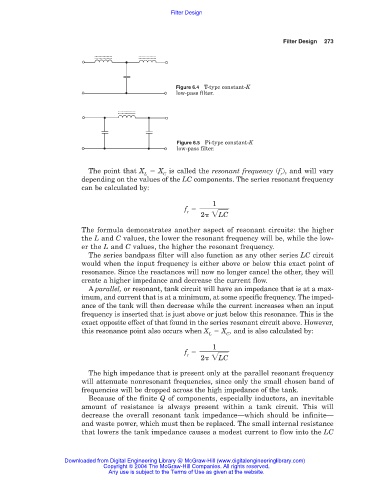
Figure 6.4 T-type constant-K
low-pass filter.
Figure 6.5 Pi-type constant-K
low-pass filter.
The point that X X is called the resonant frequency (f ), and will vary
L C r
depending on the values of the LC components. The series resonant frequency
can be calculated by:
1
f
r
2 LC
The formula demonstrates another aspect of resonant circuits: the higher
the L and C values, the lower the resonant frequency will be, while the low-
er the L and C values, the higher the resonant frequency.
The series bandpass filter will also function as any other series LC circuit
would when the input frequency is either above or below this exact point of
resonance. Since the reactances will now no longer cancel the other, they will
create a higher impedance and decrease the current flow.
A parallel, or resonant, tank circuit will have an impedance that is at a max-
imum, and current that is at a minimum, at some specific frequency. The imped-
ance of the tank will then decrease while the current increases when an input
frequency is inserted that is just above or just below this resonance. This is the
exact opposite effect of that found in the series resonant circuit above. However,
this resonance point also occurs when X X , and is also calculated by:
L C
1
f
r
2 LC
The high impedance that is present only at the parallel resonant frequency
will attenuate nonresonant frequencies, since only the small chosen band of
frequencies will be dropped across the high impedance of the tank.
Because of the finite Q of components, especially inductors, an inevitable
amount of resistance is always present within a tank circuit. This will
decrease the overall resonant tank impedance—which should be infinite—
and waste power, which must then be replaced. The small internal resistance
that lowers the tank impedance causes a modest current to flow into the LC
Downloaded from Digital Engineering Library @ McGraw-Hill (www.digitalengineeringlibrary.com)
Copyright © 2004 The McGraw-Hill Companies. All rights reserved.
Any use is subject to the Terms of Use as given at the website.