
Page 273 - Complete Wireless Design
P. 273
Filter Design
272 Chapter Six
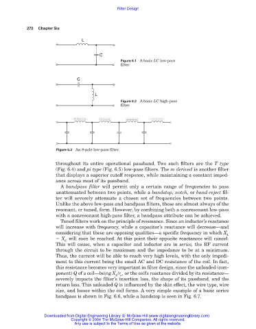
Figure 6.1 A basic LC low-pass
filter.
Figure 6.2 A basic LC high-pass
filter.
Figure 6.3 An 8-pole low-pass filter.
throughout its entire operational passband. Two such filters are the T type
(Fig. 6.4) and pi type (Fig. 6.5) low-pass filters. The m derived is another filter
that displays a superior cutoff response, while maintaining a constant imped-
ance across most of its passband.
A bandpass filter will permit only a certain range of frequencies to pass
unattenuated between two points, while a bandstop, notch, or band-reject fil-
ter will severely attenuate a chosen set of frequencies between two points.
Unlike the above low-pass and bandpass filters, these are almost always of the
resonant, or tuned, form. However, by combining both a nonresonant low-pass
with a nonresonant high-pass filter, a bandpass attribute can be achieved.
Tuned filters work on the principle of resonance. Since an inductor’s reactance
will increase with frequency, while a capacitor’s reactance will decrease—and
considering that these are opposing qualities—a specific frequency in which X
L
X will soon be reached. At this point their opposite reactances will cancel.
C
This will cause, when a capacitor and inductor are in series, the RF current
through the circuit to be maximum and the impedance to be at a minimum.
Thus, the current will be able to reach very high levels, with the only impedi-
ment to this current being the small AC and DC resistance of the coil. In fact,
this resistance becomes very important in filter design, since the unloaded (com-
ponent) Q of a coil—being X /r , or the coil’s reactance divided by its resistance—
L e
severely impacts the filter’s insertion loss, the shape of its passband, and the
return loss. This unloaded Q is influenced by the skin effect, the wire type, wire
size, and losses within the coil forms. A very simple example of a basic series
bandpass is shown in Fig. 6.6, while a bandstop is seen in Fig. 6.7.
Downloaded from Digital Engineering Library @ McGraw-Hill (www.digitalengineeringlibrary.com)
Copyright © 2004 The McGraw-Hill Companies. All rights reserved.
Any use is subject to the Terms of Use as given at the website.