
Page 275 - Complete Wireless Design
P. 275
Filter Design
274 Chapter Six
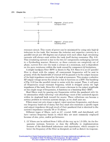
Figure 6.6 A basic series
bandpass filter.
Figure 6.7 A basic series
bandstop filter.
resonant circuit. This waste of power can be minimized by using only high-Q
inductors in the tank. But because the inductor and capacitor currents in a
parallel circuit are 180 degrees out of phase with each other, high circulating
currents will always exist within the tank itself during resonance (Fig. 6.8).
This circulating current is due to the two LC components exchanging current
in a flywheeling manner. However, as these currents are completely out of
phase, current flow into the tank is always at a minimum, and is dependent
on the pure resistance within the tank caused by component Q limitations.
A simple bandpass filter (BPF) is shown in Fig. 6.9. Since it is an LC parallel
filter in shunt with the output, all nonresonant frequencies will be sent to
ground, while the bandwidth of interest will be passed on to the output because
of the high impedance created by the tank at resonance. This creates a selective
RF output voltage across the circuit so that it functions as a BPF. The bandstop
of Fig. 6.10 has the parallel circuit in series with the output. Thus, it will pass
all frequencies except resonant frequency, which is dropped across the high
impedance of the tank. Since this will cause a decrease in the output amplitude
at this single range of frequencies, it functions as a bandstop filter (BSF).
Most filters work by passing any frequencies within the passband with lit-
tle attenuation while reflecting—not absorbing—most of the undesired signals
within its stopband back toward the source. These reflections can become a
serious problem in wireless systems design, as we shall soon see.
Filters must not only shape a signal, reject spurious frequencies, and choose
one frequency band out of many, but they must also maintain a specific input
and output impedance through much of their passband that is identical to the
system’s impedance (usually 50 or 75 ohms).
Different types of filters, such as LC, crystal, SAW, and distributed, will
have various frequency bands in which they are most commonly employed
because of size, price, and/or performance:
1. LC filters can be utilized from 1 kHz all the way up to 1.5 GHz. As the fre-
quencies increase, however, so does the difficulty in implementation
because of the distributed inductance and capacitance, which conspire to
lower the frequency of the filter as designed, as well as distort its response.
Downloaded from Digital Engineering Library @ McGraw-Hill (www.digitalengineeringlibrary.com)
Copyright © 2004 The McGraw-Hill Companies. All rights reserved.
Any use is subject to the Terms of Use as given at the website.