
Page 3 - Complete Wireless Design
P. 3
Wireless Essentials
2 Chapter One
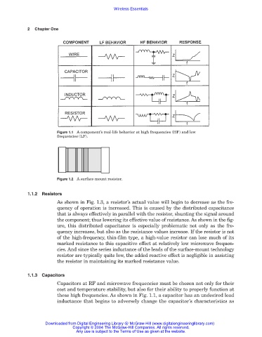
Figure 1.1 A component’s real-life behavior at high frequencies (HF) and low
frequencies (LF).
Figure 1.2 A surface mount resistor.
1.1.2 Resistors
As shown in Fig. 1.3, a resistor’s actual value will begin to decrease as the fre-
quency of operation is increased. This is caused by the distributed capacitance
that is always effectively in parallel with the resistor, shunting the signal around
the component; thus lowering its effective value of resistance. As shown in the fig-
ure, this distributed capacitance is especially problematic not only as the fre-
quency increases, but also as the resistance values increase. If the resistor is not
of the high-frequency, thin-film type, a high-value resistor can lose much of its
marked resistance to this capacitive effect at relatively low microwave frequen-
cies. And since the series inductance of the leads of the surface-mount technology
resistor are typically quite low, the added reactive effect is negligible in assisting
the resistor in maintaining its marked resistance value.
1.1.3 Capacitors
Capacitors at RF and microwave frequencies must be chosen not only for their
cost and temperature stability, but also for their ability to properly function at
these high frequencies. As shown in Fig. 1.1, a capacitor has an undesired lead
inductance that begins to adversely change the capacitor’s characteristics as
Downloaded from Digital Engineering Library @ McGraw-Hill (www.digitalengineeringlibrary.com)
Copyright © 2004 The McGraw-Hill Companies. All rights reserved.
Any use is subject to the Terms of Use as given at the website.