
Page 4 - Complete Wireless Design
P. 4
Wireless Essentials
Wireless Essentials 3
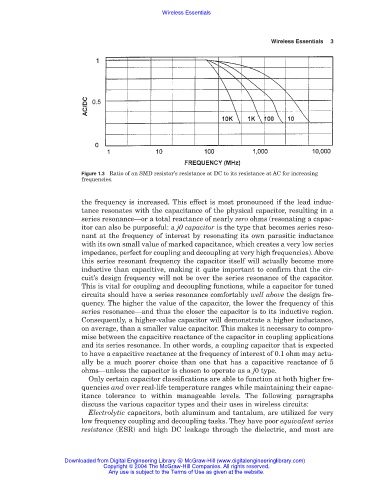
Figure 1.3 Ratio of an SMD resistor’s resistance at DC to its resistance at AC for increasing
frequencies.
the frequency is increased. This effect is most pronounced if the lead induc-
tance resonates with the capacitance of the physical capacitor, resulting in a
series resonance—or a total reactance of nearly zero ohms (resonating a capac-
itor can also be purposeful: a j0 capacitor is the type that becomes series reso-
nant at the frequency of interest by resonating its own parasitic inductance
with its own small value of marked capacitance, which creates a very low series
impedance, perfect for coupling and decoupling at very high frequencies). Above
this series resonant frequency the capacitor itself will actually become more
inductive than capacitive, making it quite important to confirm that the cir-
cuit’s design frequency will not be over the series resonance of the capacitor.
This is vital for coupling and decoupling functions, while a capacitor for tuned
circuits should have a series resonance comfortably well above the design fre-
quency. The higher the value of the capacitor, the lower the frequency of this
series resonance—and thus the closer the capacitor is to its inductive region.
Consequently, a higher-value capacitor will demonstrate a higher inductance,
on average, than a smaller value capacitor. This makes it necessary to compro-
mise between the capacitive reactance of the capacitor in coupling applications
and its series resonance. In other words, a coupling capacitor that is expected
to have a capacitive reactance at the frequency of interest of 0.1 ohm may actu-
ally be a much poorer choice than one that has a capacitive reactance of 5
ohms—unless the capacitor is chosen to operate as a j0 type.
Only certain capacitor classifications are able to function at both higher fre-
quencies and over real-life temperature ranges while maintaining their capac-
itance tolerance to within manageable levels. The following paragraphs
discuss the various capacitor types and their uses in wireless circuits:
Electrolytic capacitors, both aluminum and tantalum, are utilized for very
low frequency coupling and decoupling tasks. They have poor equivalent series
resistance (ESR) and high DC leakage through the dielectric, and most are
Downloaded from Digital Engineering Library @ McGraw-Hill (www.digitalengineeringlibrary.com)
Copyright © 2004 The McGraw-Hill Companies. All rights reserved.
Any use is subject to the Terms of Use as given at the website.