
Page 53 - Complete Wireless Design
P. 53
Modulation
52 Chapter Two
modified at the rate of the baseband’s own amplitude and frequency varia-
tions. In fact, if the amplitude of the baseband signal increases, then so will
the amplitude of the RF carrier (Fig. 2.2), while decreasing the baseband’s
amplitude decreases the amplitude of the carrier (Fig. 2.3).
The baseband modulation travels with the RF carrier to the receiver. The
receiver then takes these amplitude variations that are riding on the carrier and
removes them, thus converting them back into the original audio amplitude
variations that were inserted at the transmitter. The recovered baseband is then
amplified and fed into a speaker, or some other appropriate transducer. The per-
cent of modulation controls the final amplitude of the detected signal, and the
higher the amplitude of the baseband signal, the higher the volume at the
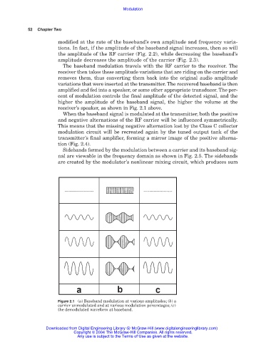
receiver’s speaker, as shown in Fig. 2.1 above.
When the baseband signal is modulated at the transmitter, both the positive
and negative alternations of the RF carrier will be influenced symmetrically.
This means that the missing negative alternation lost by the Class C collector
modulation circuit will be recreated again by the tuned output tank of the
transmitter’s final amplifier, forming a mirror image of the positive alterna-
tion (Fig. 2.4).
Sidebands formed by the modulation between a carrier and its baseband sig-
nal are viewable in the frequency domain as shown in Fig. 2.5. The sidebands
are created by the modulator’s nonlinear mixing circuit, which produces sum
Figure 2.1 (a) Baseband modulation at various amplitudes; (b) a
carrier unmodulated and at various modulation percentages; (c)
the demodulated waveform at baseband.
Downloaded from Digital Engineering Library @ McGraw-Hill (www.digitalengineeringlibrary.com)
Copyright © 2004 The McGraw-Hill Companies. All rights reserved.
Any use is subject to the Terms of Use as given at the website.