
Page 54 - Complete Wireless Design
P. 54
Modulation
Modulation 53
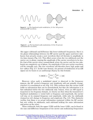
Figure 2.2 (a) The baseband audio modulation; (b) the 100 percent
modulated RF waveform.
Figure 2.3 (a) The baseband audio modulation; (b) the 50 percent
modulated RF waveform.
(the upper sideband) and difference (the lower sideband) frequencies. But it is
the phase relationships between the RF carrier and the upper and lower side-
bands that actually create a new waveform that will deviate in amplitude in
the time domain (Fig. 2.6). This effect occurs when the two sidebands and the
carrier are in phase, causing the amplitude of the carrier waveform to be dou-
ble that of the carrier when unmodulated; when the carrier and the two side-
bands are completely out of phase, the amplitude of this new carrier waveform
will be virtually zero. The new waveform will therefore have high peaks and
low valleys (Fig. 2.7). In the time domain, the percent of modulation of an AM
signal can be found on an oscilloscope display by this formula:
V V
MIN
PEAK
% MOD 100
V V
PEAK MIN
However, when such a modulated signal is observed in the frequency
domain, the RF carrier’s frequency and amplitude will not actually change,
whether it is modulated or not (Fig. 2.8). This confirms that the carrier itself
holds no information that can be demodulated, but that the information is in
fact embodied within the two sidebands only. Indeed, when an AM signal is
inspected in the frequency domain, we clearly see that when the transmitter’s
baseband modulation is varied both in frequency and amplitude, the carrier
will stay at its original frequency and amplitude, while only the sidebands
themselves will change in frequency and amplitude (Fig. 2.9). This distinctly
verifies that there is no actual information contained within the RF carrier,
but only within its sidebands, each sideband holding the same information
and power as the other.
These sidebands, both the upper (USB) and the lower (LSB), can be found at
the sum and difference frequencies of the carrier and modulating frequencies:
Downloaded from Digital Engineering Library @ McGraw-Hill (www.digitalengineeringlibrary.com)
Copyright © 2004 The McGraw-Hill Companies. All rights reserved.
Any use is subject to the Terms of Use as given at the website.