
Page 61 - Complete Wireless Design
P. 61
Modulation
60 Chapter Two
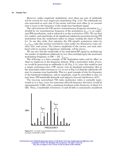
However, unlike amplitude modulation, more than one pair of sidebands
will be created for each single-tone modulation (Fig. 2.13). The sidebands are
also separated on each side of the carrier and from each other by an amount
that is equal to the frequency of the single-tone baseband signal.
The ratio between the FM carrier’s instantaneous frequency deviation (f )
DEV
divided by the instantaneous frequency of the modulation (f ) is an impor-
MOD
tant FM specification, and is referred to as the modulation index. We can find
the number and amplitudes of all significant sidebands generated during FM
modulation from the modulation index by simply reading the chart of Table
2.1. To use this table, first calculate the FM signal’s modulation index by
f /f ; take this number and find its value under the Modulation index col-
DEV MOD
umn; now read across. The relative amplitude of the carrier, and each side-
band with its number of significant sidebands, will be shown.
We can also find the bandwidth of the modulated RF signal by multiplying
the number of significant sidebands by two, then multiplying by the maximum
modulating frequency, or BW 2N f .
mod(max)
The following is a basic example of the modulation index and its effect on
what we might see in the frequency domain. With a modulation index of zero,
we would be generating no sidebands at all (Fig. 2.14), since this would be just
a simple continuous-wave (CW) carrier with no baseband modulation. But as
the modulation index increases to 1.5, we see in Fig. 2.15 that the sidebands will
start to consume more bandwidth. This is a good example of why the frequency
of the baseband modulation, and its amplitude, must be controlled so that we
may lower FM bandwidth demands and adjacent channel interference (ACI).
The two-way, narrowband FM radio modulation index is normally main-
tained at 2 or less, since the maximum allowed frequency deviation would be
approximately 5 kHz with a maximum baseband audio frequency of about 2.5
kHz. Thus, a bandwidth of between 12 and 20 kHz is customarily considered
Figure 2.13 A single-tone baseband signal creating
multiple sidebands in FM.
Downloaded from Digital Engineering Library @ McGraw-Hill (www.digitalengineeringlibrary.com)
Copyright © 2004 The McGraw-Hill Companies. All rights reserved.
Any use is subject to the Terms of Use as given at the website.