
Page 65 - Complete Wireless Design
P. 65
Modulation
64 Chapter Two
2.3.3 Modulation
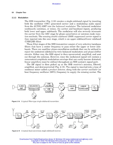
The SSB transmitter (Fig. 2.18) creates a single-sideband signal by inserting
both the oscillator (OSC) generated carrier and a modulating audio signal
from the AUDIO AMP into the balanced modulator. The balanced modulator
nonlinearly combines, or mixes, the carrier and baseband inputs, producing
both lower and upper sidebands. The modulator will also severely attenuate
the carrier from the OSC stage by phase cancellation or common-mode rejec-
tion methods. The ensuing double-sideband (DSB) suppressed carrier signal is
then injected into the next stage, which is an upper sideband/lower sideband
(USB/LSB) filter.
These filter stages of the SSB transmitter consist of very selective bandpass
filters that have a center frequency to pass either the upper or lower side-
bands. There are nonfilter phase-cancellation methods that can be utilized to
reject the undesired sideband by twin balanced modulators and phase-shifter
circuits. Either way, the SSB signal is then upconverted, amplified, and sent
out through the antenna. However, since the modulated signal will contain a
nonconstant amplitude modulation envelope that can easily become distorted,
linear amplifiers must be utilized throughout an SSB system’s signal path.
The RF signal is then picked up at the SSB receiver’s antenna, filtered,
amplified, and downconverted (Fig. 2.19). The signal is inserted into a type of
nonlinear mixer called a product detector, along with the carrier oscillator [or
beat frequency oscillator (BFO)] frequency to supply the missing carrier. The
Figure 2.18 A typical filter-type single-sideband transmitter.
Figure 2.19 A typical dual-conversion single-sideband receiver.
Downloaded from Digital Engineering Library @ McGraw-Hill (www.digitalengineeringlibrary.com)
Copyright © 2004 The McGraw-Hill Companies. All rights reserved.
Any use is subject to the Terms of Use as given at the website.