
Page 68 - Complete Wireless Design
P. 68
Modulation
Modulation 67
Figure 2.24 A phasor diagram of
phase modulation.
Figure 2.25 A phasor diagram of
amplitude modulation.
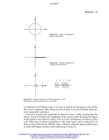
Figure 2.26 A phasor diagram of OOK modulation with
accompanying time-domain sine waveforms.
is adopted to send Morse code or to send 1s and 0s by turning on and off the
RF carrier frequency. This allows one bit of data to be sent between each dis-
crete amplitude transition.
Instead of varying the amplitude in discrete states—while maintaining the
phase—we can maintain the amplitude of the carrier while changing the phase
of the signal to two discrete states; such as 0 and 180 degrees, as shown in Fig.
2.27. This type of digital modulation is the most basic, and is referred to as
binary phase shift keying (BPSK) with a 0 degree reference phase indicating a
1, and a 180 degree discrete state indicating a binary 0.
Downloaded from Digital Engineering Library @ McGraw-Hill (www.digitalengineeringlibrary.com)
Copyright © 2004 The McGraw-Hill Companies. All rights reserved.
Any use is subject to the Terms of Use as given at the website.