
Page 67 - Complete Wireless Design
P. 67
Modulation
66 Chapter Two
2.4 Digital Modulation
2.4.1 Introduction
With the advent of digital modulation techniques, far higher data rates are pos-
sible within constrained bandwidths, and at higher reliability and noise immu-
nity levels, than the older analog modulation methods of FM, AM, frequency
shift keying (FSK), on-off keying (OOK), pulse width modulation (PWM), pulse
position modulation (PPM), pulse amplitude modulation (PAM), etc.
The newer digital modulation has much in common with some of the older
discrete digital/analog modulation methods, such as OOK and FSK, in that it
has discrete states at discrete times—whether these states are amplitude,
phase, or amplitude/phase—and these states define the information being
transmitted, while the number of states possible governs the amount of data
that can be transmitted across the link. However, digital modulation may be
considered to be only the QAM, QPSK, and BPSK modulations (defined
below), and their many variants.
2.4.2 Types of digital modulation
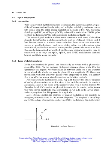
Modulation methods in general can most easily be viewed with a phasor dia-
gram (Fig. 2.23). I is the in-phase (0 degree) reference plane, while Q is the
quadrature (90 degree) reference plane. In between these two I and Q states
is the signal (S), which can vary in phase ( ) and amplitude (A). Since any
modulation will alter either the phase or the amplitude (or both) of a carrier,
this is an effective way to visualize various modulation methods.
For comparison to digital modulation, Fig. 2.24 displays the phasor diagram
of analog phase modulation which, since it has no information in its carrier’s
amplitude, shows a full circle as the carrier rotates from 0 to 360 degrees. On
the other hand, AM contains no phase information in its carrier, so its phasor
will vary only in amplitude. This is indicated in Fig. 2.25 by its carrier ampli-
tude varying from 0 to 100 percent in magnitude.
More efficient digital-like methods of analog modulation are possible by
using only discrete states in the phasor diagrams. The simplest is on-off key-
ing (OOK), a type of amplitude shift keying (ASK) modulation, Fig. 2.26, which
Figure 2.23 A phasor diagram.
Downloaded from Digital Engineering Library @ McGraw-Hill (www.digitalengineeringlibrary.com)
Copyright © 2004 The McGraw-Hill Companies. All rights reserved.
Any use is subject to the Terms of Use as given at the website.