
Page 69 - Complete Wireless Design
P. 69
Modulation
68 Chapter Two
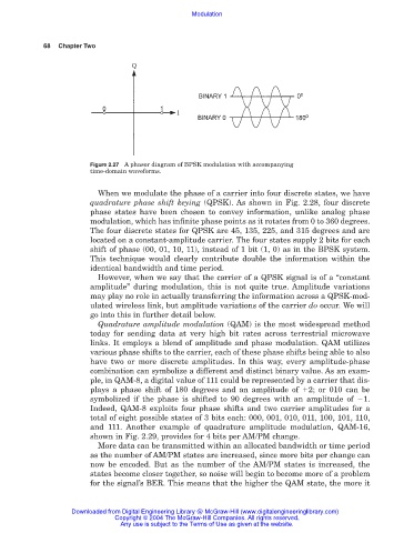
Figure 2.27 A phasor diagram of BPSK modulation with accompanying
time-domain waveforms.
When we modulate the phase of a carrier into four discrete states, we have
quadrature phase shift keying (QPSK). As shown in Fig. 2.28, four discrete
phase states have been chosen to convey information, unlike analog phase
modulation, which has infinite phase points as it rotates from 0 to 360 degrees.
The four discrete states for QPSK are 45, 135, 225, and 315 degrees and are
located on a constant-amplitude carrier. The four states supply 2 bits for each
shift of phase (00, 01, 10, 11), instead of 1 bit (1, 0) as in the BPSK system.
This technique would clearly contribute double the information within the
identical bandwidth and time period.
However, when we say that the carrier of a QPSK signal is of a “constant
amplitude” during modulation, this is not quite true. Amplitude variations
may play no role in actually transferring the information across a QPSK-mod-
ulated wireless link, but amplitude variations of the carrier do occur. We will
go into this in further detail below.
Quadrature amplitude modulation (QAM) is the most widespread method
today for sending data at very high bit rates across terrestrial microwave
links. It employs a blend of amplitude and phase modulation. QAM utilizes
various phase shifts to the carrier, each of these phase shifts being able to also
have two or more discrete amplitudes. In this way, every amplitude-phase
combination can symbolize a different and distinct binary value. As an exam-
ple, in QAM-8, a digital value of 111 could be represented by a carrier that dis-
plays a phase shift of 180 degrees and an amplitude of 2; or 010 can be
symbolized if the phase is shifted to 90 degrees with an amplitude of 1.
Indeed, QAM-8 exploits four phase shifts and two carrier amplitudes for a
total of eight possible states of 3 bits each: 000, 001, 010, 011, 100, 101, 110,
and 111. Another example of quadrature amplitude modulation, QAM-16,
shown in Fig. 2.29, provides for 4 bits per AM/PM change.
More data can be transmitted within an allocated bandwidth or time period
as the number of AM/PM states are increased, since more bits per change can
now be encoded. But as the number of the AM/PM states is increased, the
states become closer together, so noise will begin to become more of a problem
for the signal’s BER. This means that the higher the QAM state, the more it
Downloaded from Digital Engineering Library @ McGraw-Hill (www.digitalengineeringlibrary.com)
Copyright © 2004 The McGraw-Hill Companies. All rights reserved.
Any use is subject to the Terms of Use as given at the website.