
Page 71 - Complete Wireless Design
P. 71
Modulation
70 Chapter Two
whether or not it is transporting any data; this is due to the coding and encryp-
tion added to the RF signal.
2.4.3 Power and digital signals
In describing these digital modulation formats, we display either a static con-
stellation diagram or a phasor diagram at a discrete point in time and com-
pletely ignore how these transitions from symbol to symbol occur. These
transitions are especially important in the common four-phase state QPSK
modulation format and its variants, because this governs whether the modula-
tion will have a constant modulation envelope, or one that varies in amplitude.
A constant-amplitude modulation envelope will allow the use of an efficient,
near-saturated power amplifier that does not need to be backed off in its pow-
er output, while a QPSK modulation with a nonconstant amplitude requires a
highly inefficient linear amplifier that must be heavily backed off from its max-
imum power output in order to avoid massive spectral regrowth. (Too much
spectral regrowth, a form of IMD, will cause an otherwise legal signal to cause
interference to channels on either side of its own channel, and a bandpass that
no longer fits within the mandated FCC spectral mask limits.) The problem of
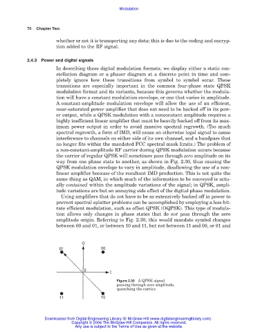
a non-constant-amplitude RF carrier during QPSK modulation occurs because
the carrier of regular QPSK will sometimes pass through zero amplitude on its
way from one phase state to another, as shown in Fig. 2.30, thus causing the
QPSK modulation envelope to vary in amplitude, disallowing the use of a non-
linear amplifier because of the resultant IMD production. This is not quite the
same thing as QAM, in which much of the information to be conveyed is actu-
ally contained within the amplitude variations of the signal; in QPSK, ampli-
tude variations are but an annoying side effect of the digital phase modulation.
Using amplifiers that do not have to be as extensively backed off in power to
prevent spectral splatter problems can be accomplished by employing a less bit-
rate efficient modulation, such as offset QPSK (OQPSK). This type of modula-
tion allows only changes in phase states that do not pass through the zero
amplitude origin. Referring to Fig. 2.30, this would mandate symbol changes
between 00 and 01, or between 10 and 11, but not between 11 and 00, or 01 and
Figure 2.30 A QPSK signal
passing through zero amplitude,
quenching the carrier.
Downloaded from Digital Engineering Library @ McGraw-Hill (www.digitalengineeringlibrary.com)
Copyright © 2004 The McGraw-Hill Companies. All rights reserved.
Any use is subject to the Terms of Use as given at the website.