Page 75 - Complete Wireless Design
P. 75

Modulation


            74  Chapter Two

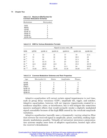
                        TABLE 2.2 Maximum Bits/Symbol for
                        Common Modulation Schemes
                        Modulation          Bits/symbol

                         MSK                    1
                         BPSK                   1
                         QPSK                   2
                         QAM-16                 4
                         QAM-32                 5
                         QAM-64                 6
                         QAM-256                8


                        TABLE 2.3 SNR for Various Modulation Formats
                                                       Signal-to-noise ratio, dB
                        BER      QPSK     QAM-16     QAM-32     QAM-64    QAM-128     QAM-256

                        10  4     8        13         15         17         19          21.5
                           5
                        10       10        14         16         18         20.5        23
                        10  5    11        15         17         19         21.5        24
                           7
                        10       12        15.75      18         20         22.5        25
                        10  8    12.5      16.25      18.5       21         23.5        25.75
                           9
                        10       13        16.5       19         21.5       24          26.25
                        10  10   13.25     16.75      19.25      21.25      24.25       26.5

                        TABLE 2.4 Common Modulation Schemes and Their Properties

                          type      Bits/symbol (h)  States   Amplitudes    Phases
                        BPSK             1            2           1           2
                        QPSK             2            4           1           4
                        PSK-8            3            8           1           8
                        QAM-16           4           16           3          12
                        QAM-32           5           32           5          28
                        QAM-64           6           64           9          52

                          Adaptive equalization will correct certain signal impairments in real time,
                        such as group delay variations (GDV), amplitude tilt, ripple, and notches.
                        Adaptive equalization, however, will not improve impairments created by a
                        nonlinear amplifier, noise, or interference, but it will mitigate the sometimes
                        massive multipath effects that would normally render a digitally modulated
                        signal unreadable because of the high BER caused by the resultant amplitude
                        variations.
                          Adaptive equalization basically uses a dynamically varying adaptive filter
                        that corrects the received signal in amplitude, phase, and delay, making high-
                        density modulations possible. Virtually all terrestrial microwave communica-
                        tion systems employ some form of adaptive equalization, located right after
                        the receiver’s demodulator.


                   Downloaded from Digital Engineering Library @ McGraw-Hill (www.digitalengineeringlibrary.com)
                               Copyright © 2004 The McGraw-Hill Companies. All rights reserved.
                                Any use is subject to the Terms of Use as given at the website.
   70   71   72   73   74   75   76   77   78   79   80