Page 263 - Compression Machinery for Oil and Gas
P. 263

248 SECTION    II Types of Equipment


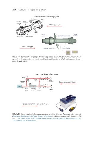
                                 Instrumented coupling types
                              Strain gages
                            Bonded to
                      Rotary
                            spool
                Industrial
                      transformer
                coupling
                                              Strain gage type
                                 Strain
                                 gages
                                                                     Driven
                                       Driving
                                                      Intermeshed pickup teeth  machine
                                       machine
                         Stator support
                 Electronics
                     Phase shift type
                                                          Flexible coupling
                                         Monopole sensors
                                                                    Display
                                                              Cond.  unit
                                                               unit
            FIG. 5.58 Instrumented couplings—typical components. (From Bill Meier, Dave Edeson, Devel-
            opments in Continuous Torque Monitoring Couplings, Presented at Ethylene Producers’ Confer-
            ence, Orlando, FL.)


                                 Laser rotational vibrometers
                                           f
                     Mirror
                                           o
                                Beam   f +  f +  f
                                       o  b  d
                                              Photo
                           f    splitter
                           o
                   Reference
                                              detector
                                                       Basic Operating Principle
                    beam
                            Test
                           beam
                                         f +  f +  f
                                           b
                                         o   d
                 Laser
                     f                   f +  f
                      o      Bragg cell  o  b
                        Beam        Beam
                                              Target
                             f +  f
                        splitter  o  b  dplitter
                     Representative twin beam portable unit
            FIG. 5.59 Laser rotational vibrometer operating principle. (Sources: Basic operating principle
            (http://en.wikipedia.org/wiki/Laser_Doppler_vibrometer) and Representative twin beam portable
            unit  (http://www.polytec.com/us/products/vibration-sensors/special-application-vibrometers/rlv-
            5500-rotational-laser-vibrometer/.)
   258   259   260   261   262   263   264   265   266   267   268