
Page 262 - Compression Machinery for Oil and Gas
P. 262
Reciprocating Compressors Chapter 5 247
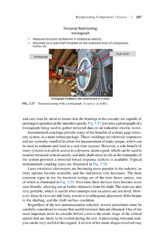
FIG. 5.57 Torsional testing with a torsiograph. (Courtesy of SwRI.)
and care must be taken to ensure that the bearings in the encoder are capable of
prolonged operation at the intended speeds. Fig. 5.57 provides a photograph of a
torsiograph being used to gather torsional data on an industrial electric motor.
Instrumented couplings provide many of the benefits of a strain gage telem-
etry system, in a more robust package. These couplings are relatively expensive
and are normally installed to allow for measurement of static torque, which can
be used to estimate unit load in a real-time manner. However, a side benefit of
many systems is to allow access to a dynamic strain signal, which can be used to
monitor torsional critical speeds, and infer shaft stress levels in the remainder of
the system provided a torsional forced response analysis is available. Typical
instrumented coupling types are illustrated in Fig. 5.58.
Laser rotational vibrometers are becoming more popular in the industry, as
more options become available, and the instrument cost decreases. The most
common types in use for torsional testing are of the twin beam variety, one
of which is illustrated in Fig. 5.59. Over time these devices have become more
user friendly, allowing use at further distances from the shaft. The units are also
very portable, which is useful when multiple test locations are involved. How-
ever, these devices are still fairly sensitive to orthogonal placement of the beams
to the shafting, and the shaft surface condition.
Regardless of the test instrumentation selected, several procedures must be
carefully considered to ensure that useful torsional data are obtained. One of the
most important items to consider before a test is the mode shape of the critical
speeds that are likely to be excited during the test. A preexisting torsional anal-
ysis can be very useful in this regard. A review of the mode shapes involved may