
Page 292 - Compression Machinery for Oil and Gas
P. 292
Screw Compressors Chapter 6 277
with all of the internal components of the machine. With this arrangement, there
is a separate oil outlet connection on the machine, through which most of the
injected seal oil returns to the reservoir of the separate seal oil system, where
it is pumped to a higher pressure, cooled, filtered, and reinjected into the
machine, and the cycle continues. By observing the oil level in the reservoir,
the total oil leakage can be monitored. The outboard leakage can be directly
measured via a separate container. The inboard leakage is simply the difference
between the total oil leakage and the measured outboard leakage. Thus, the
health of both seals can be monitored independently. When the leakage of either
the inboard or outboard seal exceeds the allowable limit, it will be indicated by
the loss of oil in the reservoir, which should trigger a shutdown of the machine.
The double mechanical seal must be designed such that either of the two seals
can individually provide a positive shut-off when the other fails.
Thermodynamic Behavior
Suction Flow and Power Consumption Versus Compressor Speed
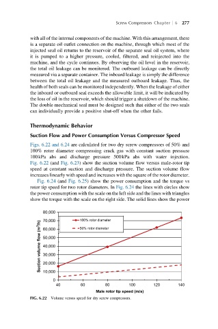
Figs. 6.22 and 6.24 are calculated for two dry screw compressors of 50% and
100% rotor diameter compressing crack gas with constant suction pressure
100kPa abs and discharge pressure 500kPa abs with water injection.
Fig. 6.22 (and Fig. 6.23) show the suction volume flow versus male-rotor tip
speed at constant suction and discharge pressure. The suction volume flow
increases linearly with speed and increases with the square of the rotor diameter.
Fig. 6.24 (and Fig. 6.25) show the power consumption and the torque vs
rotor tip speed for two rotor diameters. In Fig. 6.24 the lines with circles show
the power consumption with the scale on the left side and the lines with triangles
show the torque with the scale on the right side. The solid lines show the power
80,000 100% rotor diameter
Suction volume flow (m 3 /h) 60,000
70,000
50% rotor diameter
50,000
40,000
30,000
20,000
10,000
0
40 60 80 100 120 140
Male rotor tip speed (m/s)
FIG. 6.22 Volume versus speed for dry screw compressors.