
Page 294 - Compression Machinery for Oil and Gas
P. 294
Screw Compressors Chapter 6 279
and torque for a machine with 100% rotor diameter, and the dotted lines show
the power and torque for a machine with 50% rotor diameter.
For constant pressures the power consumption increases nearly linearly with
speed and the torque is nearly constant. At constant speed the power consump-
tion increases with the square of the rotor diameter and the torque with the cube
of the rotor diameter.
As a rule of the thumb 50% speed results in 50% suction flow and saves 50%
power. Therefore, speed variation is a very good method of process control.
The upper limit for speed variation is given by the first lateral critical speed
of the rotors including a safety margin. The lower limit is not a fixed value but is
normally given by a drop of efficiency and an increase in discharge temperature.
With a slide valve available for capacity control in oil-flooded screw com-
pressors, the difference in power consumption between capacity control via
slide valve and via VFD should be carefully considered. Capacity control via
VFD is almost always more efficient than by using the slide valve (refer to
Fig. 6.35). Although the exact difference varies by application and machine,
it is always true that the greater the turndown from 100% flow, the greater
the disparity in efficiency between VFD and slide valve. This is due to the fact
that when using the slide valve for capacity control, the machine is still running
at full speed—this uses a certain amount of energy regardless of how much
gas is flowing through the machine. When deciding whether to use the slide
valve or a VFD for capacity control in a new installation, consideration should
be given to how far from 100% flow the machine will be operated, how often,
and for how long. TCO, maintenance, and operating simplicity should also be
considered.
Actual Suction Volume Flow Versus Pressure Ratio
Fig. 6.26 shows the suction volume flow versus discharge pressure. The same
characteristics is valid for suction volume flow versus pressure ratio p 2 /p 1 .
Compressor speed and gas molecular weight are kept constant. The pressure
ratio may change by variation of the suction pressure or of the discharge pres-
sure. In both cases the suction volume flow drops slightly with increasing pres-
sure ratio but there is no surging. The limitation in pressure ratio is given by
discharge temperature, mechanical limits like bearing load or shaft stress, over-
compression or undercompression, and efficiency drop.
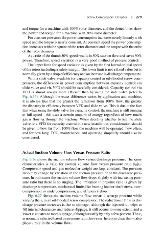
Fig. 6.27 shows the suction volume flow versus discharge pressure while
varying the v i in an oil-flooded screw compressor. The reduction in flow as dis-
charge pressure increases is due to slippage. Although the injected oil helps to
fill internal clearances and reduce slippage, it still occurs to some extent, and a
lower v i equates to more slippage, although usually by only a few percent. The v i
is normally selected based on pressure ratio; however, here it is clear that v i also
plays a role in the volume flow.