
Page 418 - Compression Machinery for Oil and Gas
P. 418
Midstream Chapter 9 397
6. Soil loading should be designed for a minimum soil safety factor of 2.0
when a detailed soil report has been obtained, and the coring for the report
was taken within 1ft. of the foundation. Other foundations are typically
designed for a minimum safety factor of 3.0.
7. Adding special mixtures (like lime, plasticizers, fly ash) in concrete foun-
dations should be carefully selected, core tested, and monitored. Improper
use can cause a foundation to fail under design loads.
8. Design of foundations below the water table must include buoyancy design
considerations.
9. Typical ranges for allowable maximum bearing capacity on soils (above
the water table) are between 95 and 190kPa (sands or clay).
10. For shallow foundations and colder climates, the top 1–1.5m of soil is gen-
erally considered to be unacceptable for use and must be replaced by a
compacted back fill, or have the foundation penetrate below the 1–1.5m
depth.
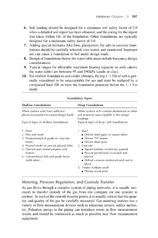
Foundation Types
Shallow Foundations Deep Foundations
When surface soils have sufficient When surface soils contain deleterious or other
physical properties to sustain design loads soil materials unacceptable to the design
loadings
Typical types of shallow foundations: Typical types of deep / pile foundations:
1. Piers 1. Steel
2. Pier and beam l Drilled steel pipes or square tubes
3. Posttensioned at grade w/ concrete l Driven “H” beams
forms l Driven sheet piles
4. Poured onsite-or-precast placed slabs 2. Concrete
5. Formed and reinforced piers and l Square formed, reinforced, poured
footers l Precast prestressed excavated and
6. Conventional slab and grade beam placed
(with rebar) l Drilled caissons reinforced and cast in
place
3. Timber (seldom used)
l Driven wood piles
Metering, Pressure Regulation, and Custody Transfer
As gas flows through a complex system of piping networks, it is usually nec-
essary to transfer custody of the gas from one company (or one system) to
another. At each of the custody transfer points, it is usually critical that the quan-
tity and quality of the gas be carefully measured. Gas metering stations use a
variety of flow measurement devices such as ultrasonic meters, orifice meters,
etc. Pulsation energy in the piping can introduce errors in flow measurement
results and should be minimized as much as possible near flow measurement
equipment.