
Page 428 - Compression Machinery for Oil and Gas
P. 428
Downstream Chapter 10 407
These compressors do not generally present technical challenges other than
those normally related to trains involving multiple large units.
Subcooling service can be accomplished by two or three casings (horizon-
tally split and/or barrel design). The critical aspect of this service is the low-
temperature material selection requirements.
Typically the material chosen for such low-temperature service is steel with
9% nickel (ASTM A522).
Double-Flow Compressors
As LNG plant capacities increase, centrifugal compressor casings can become
very large. To minimize compressor casing size, a double-flow arrangement can
be used. The inlet flow enters the casing via two nozzles and passes through
each individual section of the compressor and joins at the final diffuser exiting
the casing through a single nozzle. The advantage of the double-flow arrange-
ment is that the same casing size can accommodate a large volume flow. Losses
in the flow paths through a double-flow compressor must be identical. In prac-
tice, this is difficult to achieve and the sensitivity is a function of the total head
level. The lower the head level, the closer the flow paths in the compressor
should be. Another considerable advantage of a double-flow compressor design
is that an optimum speed match can be derived with the next stage casing.
Double-flow compressors have a limitation on the number of stages and there-
fore on pressure ratio and this can lead to an additional casing being required for
higher pressure ratios.
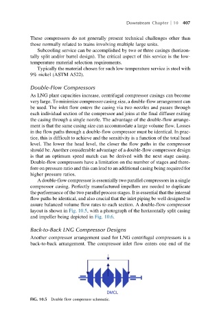
A double-flow compressor is essentially two parallel compressors in a single
compressor casing. Perfectly manufactured impellers are needed to duplicate
the performance of the two parallel process stages. It is essential that the internal
flow paths be identical, and also crucial that the inlet piping be well designed to
assure balanced volume flow rates to each section. A double-flow compressor
layout is shown in Fig. 10.5, with a photograph of the horizontally split casing
and impeller being depicted in Fig. 10.6.
Back-to-Back LNG Compressor Designs
Another compressor arrangement used for LNG centrifugal compressors is a
back-to-back arrangement. The compressor inlet flow enters one end of the
DMCL
FIG. 10.5 Double flow compressor schematic.