
Page 429 - Compression Machinery for Oil and Gas
P. 429
408 SECTION III Applications
FIG. 10.6 Double flow compressor casing and rotor.
2BCL
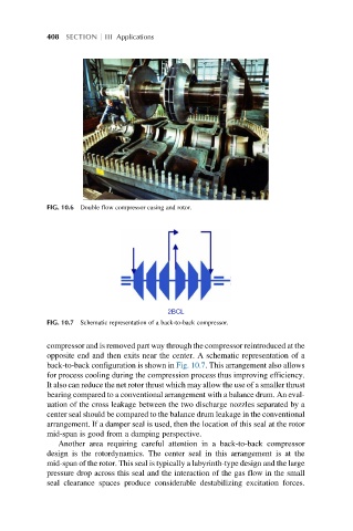
FIG. 10.7 Schematic representation of a back-to-back compressor.
compressor and is removed part way through the compressor reintroduced at the
opposite end and then exits near the center. A schematic representation of a
back-to-back configuration is shown in Fig. 10.7. This arrangement also allows
for process cooling during the compression process thus improving efficiency.
It also can reduce the net rotor thrust which may allow the use of a smaller thrust
bearing compared to a conventional arrangement with a balance drum. An eval-
uation of the cross leakage between the two discharge nozzles separated by a
center seal should be compared to the balance drum leakage in the conventional
arrangement. If a damper seal is used, then the location of this seal at the rotor
mid-span is good from a damping perspective.
Another area requiring careful attention in a back-to-back compressor
design is the rotordynamics. The center seal in this arrangement is at the
mid-span of the rotor. This seal is typically a labyrinth-type design and the large
pressure drop across this seal and the interaction of the gas flow in the small
seal clearance spaces produce considerable destabilizing excitation forces.