
Page 64 - Compression Machinery for Oil and Gas
P. 64
Centrifugal Compressors Chapter 3 55
the gas while flowing from the diameter at the impeller inlet (u 1 ¼ πD i N) to the
higher diameter at the impeller exit (u 2 ¼ πD tip N).
The importance of the Euler’s law lies in the fact that it connects aerody-
namic considerations (i.e., the velocities involved) with the thermodynamics
of the compression process.
Operating Regimes of a Centrifugal Compressor
The general behavior of any gas compressor can be gauged by some additional,
fundamental relationships: the vanes of the rotating impeller “see” the gas in a
coordinate system that rotates with the impeller. The transformation of velocity
coordinates from an absolute frame of reference (c) to the frame of reference
rotating with a velocity u is by
! ! !
w¼c u
where, for any diameter D of the impeller u ¼ πDN.
The impeller exit geometry (“backsweep”) determines the direction of the
relative velocity w 2 at the impeller exit. The basic “ideal“ slope of head versus
flow is dictated by the kinematic flow relationship of the compressor, in partic-
ular the amount of backsweep of the impeller. Any (Fig. 3.25) increase in flow
at constant speed causes a reduction of the circumferential component of the
absolute exit velocity (c u2 ). It follows from the Euler’s equation above, that this
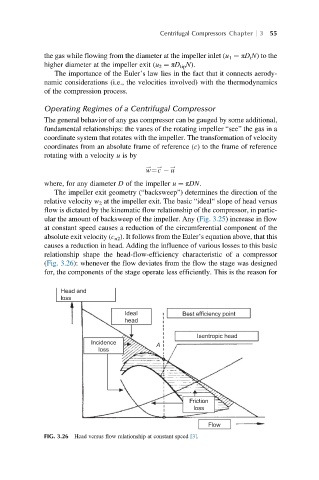
causes a reduction in head. Adding the influence of various losses to this basic
relationship shape the head-flow-efficiency characteristic of a compressor
(Fig. 3.26): whenever the flow deviates from the flow the stage was designed
for, the components of the stage operate less efficiently. This is the reason for
Head and
loss
Ideal Best efficiency point
head
Isentropic head
Incidence A
loss
Friction
loss
Flow
FIG. 3.26 Head versus flow relationship at constant speed [3].