
Page 65 - Compression Machinery for Oil and Gas
P. 65
56 SECTION II Types of Equipment
(A) (C)
(B) (D)
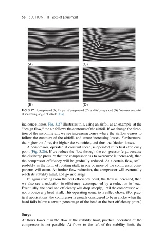
FIG. 3.27 Unseparated (A, B), partially separated (C), and fully separated (D) flow over an airfoil
at increasing angle of attack [33a].
incidence losses. Fig. 3.27 illustrates this, using an airfoil as an example: at the
“design flow,“ the air follows the contours of the airfoil. If we change the direc-
tion of the incoming air, we see increasing zones where the airflow ceases to
follow the contours of the airfoil, and create increasing losses. Furthermore,
the higher the flow, the higher the velocities, and thus the friction losses.
A compressor, operated at constant speed, is operated at its best efficiency
point (Fig. 3.26). If we reduce the flow through the compressor (e.g., because
the discharge pressure that the compressor has to overcome is increased), then
the compressor efficiency will be gradually reduced. At a certain flow, stall,
probably in the form of rotating stall, in one or more of the compressor com-
ponents will occur. At further flow reduction, the compressor will eventually
reach its stability limit, and go into surge.
If, again starting from the best efficiency point, the flow is increased, then
we also see a reduction in efficiency, accompanied by a reduction in head.
Eventually, the head and efficiency will drop steeply, until the compressor will
not produce any head at all. This operating scenario is called choke. (For prac-
tical applications, the compressor is usually considered to be in choke when the
head falls below a certain percentage of the head at the best efficiency point.)
Surge
At flows lower than the flow at the stability limit, practical operation of the
compressor is not possible. At flows to the left of the stability limit, the