
Page 100 - Computational Modeling in Biomedical Engineering and Medical Physics
P. 100
88 Computational Modeling in Biomedical Engineering and Medical Physics
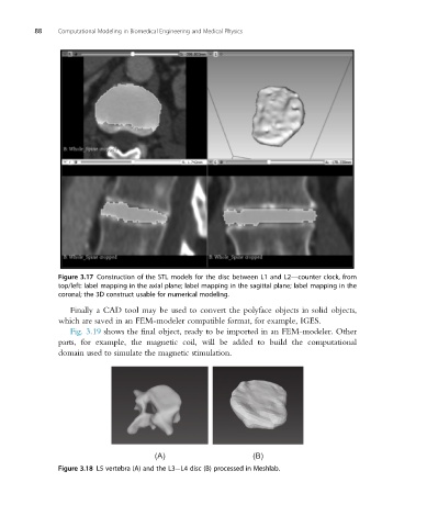
Figure 3.17 Construction of the STL models for the disc between L1 and L2—counter clock, from
top/left: label mapping in the axial plane; label mapping in the sagittal plane; label mapping in the
coronal; the 3D construct usable for numerical modeling.
Finally a CAD tool may be used to convert the polyface objects in solid objects,
which are saved in an FEM-modeler compatible format, for example, IGES.
Fig. 3.19 shows the final object, ready to be imported in an FEM-modeler. Other
parts, for example, the magnetic coil, will be added to build the computational
domain used to simulate the magnetic stimulation.
(A) (B)
Figure 3.18 L5 vertebra (A) and the L3 L4 disc (B) processed in Meshlab.