
Page 409 -
P. 409
Section 12.2 Model-based Vision: Registering Rigid Objects with Projection 377
Model Input image Overlaid
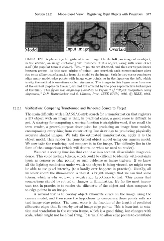
FIGURE 12.6: A plane object registered to an image. On the left, an image of an object;
in the center, an image containing two instances of this object, along with some other
stuff (the popular term is clutter). Feature points are detected, and then correspondences
between groups—in this case, triples of points—are searched; each correspondence gives
rise to an affine transformation from the model to the image. Satisfactory correspondences
align many model edge points with image edge points, as in the figure on the left,which
is why the method is sometimes called alignment. The images in this figure come from one
of the earliest papers on the subject and are affected by the poor reproduction techniques
of the time. This figure was originally published as Figure 7 of “Object recognition using
alignment,” D.P. Huttenlocher and S. Ullman, Proc. IEEE ICCV, 1986. c IEEE, 1986.
12.2.1 Verification: Comparing Transformed and Rendered Source to Target
The main difficulty with a RANSAC-style search for a transformation that registers
a 3D object with an image is that, in practical cases, a good score is difficult to
get. A strategy for computing a scoring function is straightforward, if we recall the
term render, a general-purpose description for producing an image from models,
encompassing everything from constructing line drawings to producing physically
accurate shaded images. We take the estimated transformation, apply it to the
object model, then render the transformed object model using our camera model.
We now take the rendering, and compare it to the image. The difficulty lies in the
form of the comparison (which will determine what we need to render).
We need a scoring function that can take into account all available image evi-
dence. This could include tokens, which could be difficult to identify with certainty
(such as corners or edge points) or such evidence as image texture. If we know
all the lighting conditions under which the object is being viewed, we might even
be able to use pixel intensity (this hardly ever happens in practice). Usually, all
we know about the illumination is that it is bright enough that we can find some
tokens, which is why we have a registration hypothesis to test. This means that
comparisons should be robust to changes in illumination. By far the most impor-
tant test in practice is to render the silhouette of the object and then compare it
to edge points in an image.
A natural test is to overlay object silhouette edges on the image using the
camera model, and then score the hypothesis by comparing these points with ac-
tual image edge points. The usual score is the fraction of the length of predicted
silhouette edges that lie nearby actual image edge points. This is invariant to rota-
tion and translation in the camera frame, which is a good thing, but changes with
scale, which might not be a bad thing. It is usual to allow edge points to contribute