
Page 411 -
P. 411
Section 12.3 Registering Deformable Objects 379
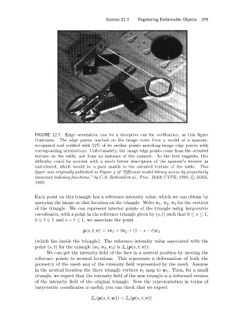
FIGURE 12.7: Edge orientation can be a deceptive cue for verification, as this figure
illustrates. The edge points marked on the image come from a model of a spanner,
recognized and verified with 52% of its outline points matching image edge points with
corresponding orientations. Unfortunately, the image edge points come from the oriented
texture on the table, not from an instance of the spanner. As the text suggests, this
difficulty could be avoided with a much better description of the spanner’s interior as
untextured, which would be a poor match to the oriented texture of the table. This
figure was originally published as Figure 4 of “Efficient model library access by projectively
invariant indexing functions,” by C.A. Rothwell et al., Proc. IEEE CVPR, 1992, c IEEE,
1992.
Each point on this triangle has a reference intensity value, which we can obtain by
querying the image at that location on the triangle. Write v 1 , v 2 , v 3 for the vertices
of the triangle. We can represent interior points of the triangle using barycentric
coordinates; with a point in the reference triangle given by (s, t) such that 0 ≤ s ≤ 1,
0 ≤ t ≤ 1and s + t ≤ 1, we associate the point
p(s, t; v)= sv 1 + tv 2 +(1 − s − t)v 3
(which lies inside the triangle). The reference intensity value associated with the
point (s, t) for the triangle (v 1 , v 2 , v 3 )is I o (p(s, t; v)).
We can get the intensity field of the face in a neutral position by moving the
reference points to neutral locations. This represents a deformation of both the
geometry of the mesh and of the intensity field represented by the mesh. Assume
in the neutral location the three triangle vertices v i map to w i . Then, for a small
triangle, we expect that the intensity field of the new triangle is a deformed version
of the intensity field of the original triangle. Now the representation in terms of
barycentric coordinates is useful; you can check that we expect
I n (p(s, t; w)) = I o (p(s, t; v))