
Page 82 -
P. 82
2.2 Photometric image formation 61
f = 100 mm
W=35mm f.o.v. P d
c
ǻz i
z i=102 mm z o=5 m
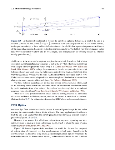
Figure 2.19 A thin lens of focal length f focuses the light from a plane a distance z o in front of the lens at a
1
distance z i behind the lens, where 1 + 1 = . If the focal plane (vertical gray line next to c) is moved forward,
z o z i f
the images are no longer in focus and the circle of confusion c (small thick line segments) depends on the distance
of the image plane motion Δz i relative to the lens aperture diameter d. The field of view (f.o.v.) depends on the
ratio between the sensor width W and the focal length f (or, more precisely, the focusing distance z i , which is
usually quite close to f).
visible) areas in the scene can be captured as a form factor, which depends on their relative
2
orientation and surface reflectance properties, as well as the 1/r fall-off as light is distributed
over a larger effective sphere the further away it is (Cohen and Wallace 1993; Sillion and
Puech 1994; Glassner 1995). A large linear system can then be set up to solve for the final
lightness of each area patch, using the light sources as the forcing function (right hand side).
Once the system has been solved, the scene can be rendered from any desired point of view.
Under certain circumstances, it is possible to recover the global illumination in a scene from
photographs using computer vision techniques (Yu, Debevec, Malik et al. 1999).
The basic radiosity algorithm does not take into account certain near field effects, such
as the darkening inside corners and scratches, or the limited ambient illumination caused
by partial shadowing from other surfaces. Such effects have been exploited in a number of
computer vision algorithms (Nayar, Ikeuchi, and Kanade 1991; Langer and Zucker 1994).
While all of these global illumination effects can have a strong effect on the appearance
of a scene, and hence its 3D interpretation, they are not covered in more detail in this book.
(But see Section 12.7.1 for a discussion of recovering BRDFs from real scenes and objects.)
2.2.3 Optics
Once the light from a scene reaches the camera, it must still pass through the lens before
reaching the sensor (analog film or digital silicon). For many applications, it suffices to
treat the lens as an ideal pinhole that simply projects all rays through a common center of
projection (Figures 2.8 and 2.9).
However, if we want to deal with issues such as focus, exposure, vignetting, and aber-
ration, we need to develop a more sophisticated model, which is where the study of optics
comes in (M¨ oller 1988; Hecht 2001; Ray 2002).
Figure 2.19 shows a diagram of the most basic lens model, i.e., the thin lens composed
of a single piece of glass with very low, equal curvature on both sides. According to the
lens law (which can be derived using simple geometric arguments on light ray refraction), the
relationship between the distance to an object z o and the distance behind the lens at which a