
Page 251 - Concise Encyclopedia of Robotics
P. 251
For high-current equipment, a full-wave rectifier is preferred. The full-
wave scheme is also better when good voltage regulation is needed. This
circuit makes use of both halves of the AC cycle to derive its DC output.
There are two basic circuits for the full-wave supply. One version uses a
center tap in the transformer, and needs two diodes. The other circuit
uses four diodes and does not require a center-tapped transformer.
The half-wave, full-wave center-tap, and bridge rectifier circuits are
shown schematically in Fig. 3.
The filter Power Supply
Electronic equipment generally does not function well with the pulsating
DC that comes straight from a rectifier. The ripple in the waveform must
be smoothed out, so that pure, battery-like DC is supplied. A filter circuit
does this.
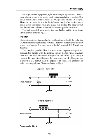
The simplest possible filter is one or more large-value capacitors,
connected in parallel with the rectifier output. Electrolytic or tantalum
capacitors are used. Sometimes a large-value coil, called a filter choke, is
connected in series, in addition to the capacitor in parallel. This provides
a smoother DC output than the capacitor by itself. Two examples of
inductance/capacitance filters are shown in Fig. 4.
Capacitor-input filter
+ +
+
From rectifier Output
Choke-input filter
+ +
+
From rectifier Output
Power supply—Fig. 4
