
Page 97 - Concise Encyclopedia of Robotics
P. 97
Dynamic Transducer
duty cycle, the shorter is the useful life. This effect is most pronounced
when a device is worked near its limits. Also, the rating of a device often
depends on the duty cycle at which it is expected to be used.
Suppose the motor described above is rated at a torque of 10 newton-
meters (10 N m) for a duty cycle of 100 percent. If the motor is called
upon to provide a constant torque of 9.9 N m, then it will be taxed to its
utmost. If it must constantly turn a load of 12 N m, it should come as no
surprise if it fails prematurely. For a duty cycle of 33 percent, the motor
might be rated at 15 N m, as long as any single working period does not
exceed 2 min. If it only needs to turn 0.5 N m, the motor can not only
run continuously, it will probably last longer than its expected life.
Devices such as robot motors can be protected from overwork (either
momentary or long-term) by means of back pressure sensors. See BACK
PRESSURE SENSOR.
DYNAMIC STABILITY
Dynamic stability is a measure of the ability of a robot to maintain its bal-
ance while in motion.
A robot with two or three legs, or that rolls on two wheels, can have
excellent stability while it is moving, but when it comes to rest, it is
unstable. A two-legged robot can be pushed over easily when it is standing
still. This is one of the major drawbacks of biped robots. It is difficult and
costly to engineer a good sense of balance, of the sort you take for granted,
into a two-legged or two-wheeled machine, although it has been done.
Robots with four or six legs have good dynamic stability, but they are
usually slower in their movements compared with machines that have
fewer legs.
See also BIPED ROBOT, INSECT ROBOT, and STATIC STABILITY.
DYNAMIC TRANSDUCER
A dynamic transducer is a coil-and-magnet device that converts mechanical
motion into electricity or vice versa. The most common examples are the
dynamic microphone and the dynamic loudspeaker. Dynamic transducers
can be used as sensors in a variety of robotic applications.
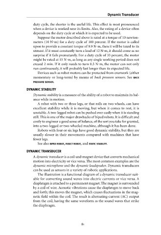
The illustration is a functional diagram of a dynamic transducer suit-
able for converting sound waves into electric currents or vice versa. A
diaphragm is attached to a permanent magnet. The magnet is surrounded
by a coil of wire. Acoustic vibrations cause the diaphragm to move back
and forth; this moves the magnet, which causes fluctuations in the mag-
netic field within the coil. The result is alternating-current (AC) output
from the coil, having the same waveform as the sound waves that strike
the diaphragm.
