
Page 54 - Construction Waterproofing Handbook
P. 54
2.18 CHAPTER TWO
TABLE 2.2 Suggested Waterstop Sizing for General Conditions (Courtesy of Vinylex Corporation)
Maximum allowable Minimum embedment
Size (flange/ head of water (per Army of flange into concrete Minimum distance
thickness), Corps Engineering Manual inches to edge of slab/wall,
inches EM 1110-22101) feet inches
3
4 16 50 1.250 2.000
3
9 16 100 2.875 2.875
3
9 8 150 2.875 2.875
1
12 2 250 4.000 4.000
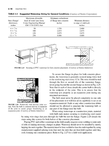
FIGURE 2.23 Securing of PVC waterstop for first concrete placement. (Courtesy of Tamms Industries)
To secure the flange in place for both concrete place-
ments, the waterstop is generally secured using wires tied
to the reinforcing steel every 12 in. The wire should be tied
through the first or second ribs of the waterstop flange,
never going beyond the second flange as shown in Fig. 2.25.
Note that in each of these details the center bulb is directly
in the midpoint of the joint. This is to ensure that the
waterstop acts properly as an expansion joint during any
structural movement.
The bulb must never be placed completely in one side
of the placement or it will lose all its capability to act as an
expansion material. Nails or any other construction debris
FIGURE 2.24 Formwork with keyway joint sys-
tem. Note the bulb is centered directly in midpoint should not be allowed to puncture the waterstop bulb or
of the joint to ensure proper functioning as an any part of the flange near the bulb.
expansion joint. (Courtesy of Tamms Industries) When using waterstops at construction joints, material
with bulb ends makes securing to reinforcing steel easier
by using wire rings that pass through the bulb but not the flange. Figure 2.26 details the
steps using this system for both halves of the concrete placement.
Placing PVC and rubber waterstops in the field usually requires some welding to joint ends
of rolls or making necessary changes in plane. Waterstop should never be installed by merely
lapping the ends together. The material must be heat-welded to fuse the ends together by using
manufacturer-supplied splicing irons that melt the ends that are then held together until they
cool, forming one continuous piece. Refer to Fig. 2.27 for a field weld application.