
Page 320 - Corrosion Engineering Principles and Practice
P. 320
290 C h a p t e r 8 C o r r o s i o n b y W a t e r 291
recirculating system versus a once-through system are maximized at
about 4 to 6 cycles of concentration. Below this range, treatment costs
become prohibitive. At high cycles (e.g., 8 to 10), the additional water
savings are not commensurate with the increased difficulty of
effective treatment. If the blowdown is shut off entirely, there is still
an effective upper limit of concentration dictated by water losses
from drift or windage. The normal upper limits might be about 20 to
22 cycles of concentration for a mechanical-draft tower.
The advantages of water savings affected by the cooling tower also
impose certain inherent disadvantages. The water becomes air
saturated, ensuring its full corrosion potential, its natural alkalinity
tends to increase and aggravate scaling tendencies. The air scrubbing
action can contaminate the water with airborne materials, notably dust
fines, which form silt in the tower basin, and spores of slime, algae, and
fungi that can reproduce in the warm nutrient water of the system.
8.4.3 Heat Exchangers
Heat is removed from exothermic processes, hot gases, and liquids,
and to control operating temperatures through heat exchangers
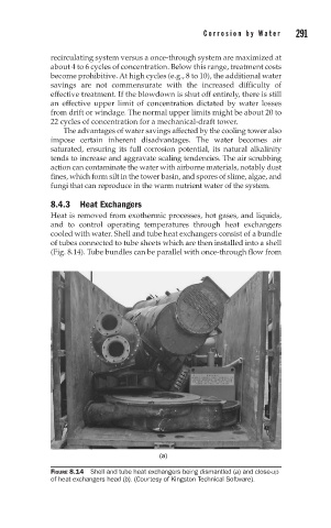
cooled with water. Shell and tube heat exchangers consist of a bundle
of tubes connected to tube sheets which are then installed into a shell
(Fig. 8.14). Tube bundles can be parallel with once-through flow from
(a)
FIGURE 8.14 Shell and tube heat exchangers being dismantled (a) and close-up
of heat exchangers head (b). (Courtesy of Kingston Technical Software).