Page 554 - Corrosion Engineering Principles and Practice
P. 554
516 C h a p t e r 1 2 C o r r o s i o n a s a R i s k 517
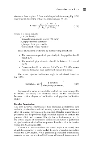
dominant flow regime. A flow modeling calculation using Eq. (12.8)
is applied to determine critical inclination angles (θ) [24]:
ρ V 2
g
θ = sin −1 ρ − g ρ × g × d × F (12.8)
l g id
where r is liquid density
l
r is gas density
g
g is acceleration due to gravity (9.8 m/s )
2
d is pipe internal diameter
id
V is superficial gas velocity
g
F is modified Froude number
These calculations are bound by the following conditions:
• The maximum superficial gas velocity in the pipeline should
be ≤ 8 m/s.
• The nominal pipe diameter should be between 0.1 m and
1.2 m.
• Pressures should be between 3.4 MPa and 7.6 MPa unless
flow modeling has been performed outside this range.
The actual pipeline inclination angle is calculated based on
Eq. (12.9):
∆ elevation
Inclination = tan −1 (12.9)
e
∆ length of pipe section
Regions with water accumulation, which are most susceptible
to internal corrosion, are identified based on the comparison
between critical degree of inclination and pipeline inclination
angles.
Detailed Examination
This step involves comparison of field-measured performance data
with the pipeline historical and existing operating data to assess the
effect of internal corrosion on the pipeline. Detailed examination is
performed on the predicted high corrosion regions to confirm the
presence of internal corrosion. If the pipeline inclination angle exceeds
the critical degree of inclination, detailed examination is performed
at pipe locations with inclination greater than the critical inclination
within the ICDA region [24].
If there is no instance where the critical angle is exceeded, then
detailed examination is performed at the angle of greatest inclination
within the ICDA region. While performing a detailed examination,
accurate measurements of wall thickness within wall loss areas need

