Page 599 - Corrosion Engineering Principles and Practice
P. 599

562    C h a p t e r   1 3                                                                                                        C a t h o d i c   P r o t e c t i o n    563


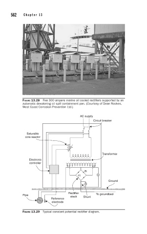
                      FIGURE 13.28  Five 300 ampere marine oil cooled rectifiers supported by an
                      automatic dewatering oil spill containment pan. (Courtesy of Dean Rookes,
                      West Coast Corrosion Prevention Ltd.)

                                                      AC supply
                                                              Circuit breaker


                        Saturable
                       core reactor


                                                                   Transformer
                          Electronic
                          controller
                                               (1)           (2)
                                                         (B)
                                                     (C)        V
                                                                      Ground
                                                         A

                                                Rectifier
                      Pipe                       stack  Shunt  To groundbed
                                      Reference
                                      electrode


                      FIGURE 13.29  Typical constant potential rectifier diagram.
   594   595   596   597   598   599   600   601   602   603   604