
Page 603 - Corrosion Engineering Principles and Practice
P. 603
566 C h a p t e r 1 3 C a t h o d i c P r o t e c t i o n 567
Point “C” contact with
remote earth to (–)
Terminal of Voltmeter
CP power Point “A”
source contact with – + When connected as shown,
close earth voltmeter will show more
– negative values when
CP system is energized
Point “B” contact
with pipeline
Groundbed
Earth
Pipe
Coating
CP power CP power
– source Point “B” + _ source
Point “B”
+
_ Pipe
+
+ –
Pipe
Polarization
Point “A” Point “C” Polarization
on earth above pipe potential Resistance of Point “A” potential
Combination of anode-to-earth groundbed anodes on earth
and pipe-to-earth resistances, to remote earth above pipe
which is less than the sum of pipe Resistance between
and anode resistances to remote earth pipeline and remote earth
Equivalent circuit 1: Pipeline Equivalent circuit 2: Groundbed
within “area of influence” of groundbed electrically remote from pipeline
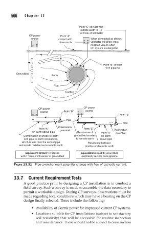
FIGURE 13.31 Pipe-to-environment potential change with flow of cathodic current.
13.7 Current Requirement Tests
A good practice prior to designing a CP installation is to conduct a
field survey. Such a survey is made to assemble the data necessary to
permit a workable design. During CP surveys, observations must be
made regarding local conditions which may have a bearing on the CP
design finally selected. These include the following:
• Availability of electric power for impressed current CP systems.
• Locations suitable for CP installations (subject to satisfactory
soil resistivity) that will be accessible for routine inspection
and maintenance. These should not be subject to construction