
Page 606 - Corrosion Engineering Principles and Practice
P. 606
568 C h a p t e r 1 3 C a t h o d i c P r o t e c t i o n 569
Temporary ground
connection
DC power
+
– source
1.7 A (Calculated) 1.2 A (Calculated)
mV mV
– – +
+
– Ammeter
59.0 A
A
Pipeline
(Bare) Current flow
Voltmeter
V V V V V
– + – + – + – +
+
–0.85 V –1.02 V –3.20 V –1.10 V –0.85 V
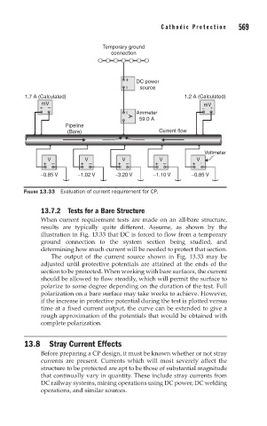
FIGURE 13.33 Evaluation of current requirement for CP.
13.7.2 Tests for a Bare Structure
When current requirement tests are made on an all-bare structure,
results are typically quite different. Assume, as shown by the
illustration in Fig. 13.33 that DC is forced to flow from a temporary
ground connection to the system section being studied, and
determining how much current will be needed to protect that section.
The output of the current source shown in Fig. 13.33 may be
adjusted until protective potentials are attained at the ends of the
section to be protected. When working with bare surfaces, the current
should be allowed to flow steadily, which will permit the surface to
polarize to some degree depending on the duration of the test. Full
polarization on a bare surface may take weeks to achieve. However,
if the increase in protective potential during the test is plotted versus
time at a fixed current output, the curve can be extended to give a
rough approximation of the potentials that would be obtained with
complete polarization.
13.8 Stray Current Effects
Before preparing a CP design, it must be known whether or not stray
currents are present. Currents which will most severely affect the
structure to be protected are apt to be those of substantial magnitude
that continually vary in quantity. These include stray currents from
DC railway systems, mining operations using DC power, DC welding
operations, and similar sources.