
Page 609 - Corrosion Engineering Principles and Practice
P. 609
572 C h a p t e r 1 3 C a t h o d i c P r o t e c t i o n 573
GPS satellite GPS satellite
synchronization synchronization
Rectifier
Test station
Reference Copper wire
electrode
Interrupter switch
Voltmeter/logger
Buried pipeline
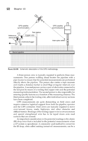
FIGURE 13.35 Schematic description of the CIPS methodology.
A three-person crew is typically required to perform these mea-
surements. One person walking ahead locates the pipeline with a
pipe locator to ensure that the potential measurements are performed
directly above the pipeline. This person also carries a tape measure
and inserts a distance marker (a small flag) at regular intervals over
the pipeline. A second person carries a pair of electrodes connected to
the test post by means of a trailing thin copper wire and the potential
measuring instrumentation. The second person is also responsible for
entering specific features as a function of the measuring distance. The
third person collects the trailing wire, after individual survey sections
have been completed.
CIPS measurements are quite demanding on field crews and
require extensive logistical support from both the pipeline operator
and the CIPS contractor. Field crews are typically required to move
over/around fences, roads, highways, and other obstacles and
difficult terrain. Breakage of the trailing copper wire is not uncommon
and special strengthened wire has to be taped down onto road
surfaces that are crossed.
An important consideration in the potential readings is the ohmic
(IR) drop error that is included in the potential measurements when
a CP system is operational. A commonly used method to correct for
the IR drop, often called making instant-off measurements, can be a