
Page 605 - Corrosion Engineering Principles and Practice
P. 605
568 C h a p t e r 1 3 C a t h o d i c P r o t e c t i o n 569
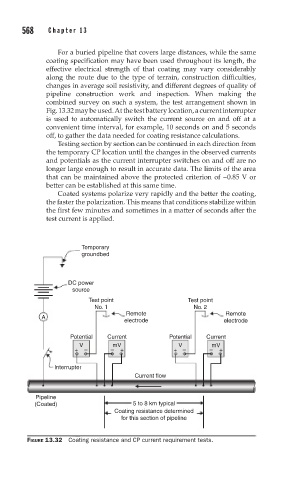
For a buried pipeline that covers large distances, while the same
coating specification may have been used throughout its length, the
effective electrical strength of that coating may vary considerably
along the route due to the type of terrain, construction difficulties,
changes in average soil resistivity, and different degrees of quality of
pipeline construction work and inspection. When making the
combined survey on such a system, the test arrangement shown in
Fig. 13.32 may be used. At the test battery location, a current interrupter
is used to automatically switch the current source on and off at a
convenient time interval, for example, 10 seconds on and 5 seconds
off, to gather the data needed for coating resistance calculations.
Testing section by section can be continued in each direction from
the temporary CP location until the changes in the observed currents
and potentials as the current interrupter switches on and off are no
longer large enough to result in accurate data. The limits of the area
that can be maintained above the protected criterion of −0.85 V or
better can be established at this same time.
Coated systems polarize very rapidly and the better the coating,
the faster the polarization. This means that conditions stabilize within
the first few minutes and sometimes in a matter of seconds after the
test current is applied.
Temporary
groundbed
DC power
source
Test point Test point
No. 1 No. 2
Remote Remote
A
electrode electrode
Potential Current Potential Current
V mV V mV
– – + + – – +
+
Interrupter
Current flow
Pipeline
(Coated) 5 to 8 km typical
Coating resistance determined
for this section of pipeline
FIGURE 13.32 Coating resistance and CP current requirement tests.