
Page 612 - Corrosion Engineering Principles and Practice
P. 612
574 C h a p t e r 1 3 C a t h o d i c P r o t e c t i o n 575
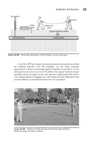
Test station
Receiver
Earth Aluminum
spike
Transmitter pole
Signal emitted at defect
X
Buried pipeline Coating defect
FIGURE 13.38 Schematic description of the Pearson survey technique.
As in the CIPS technique, the measurements are usually recorded
by walking directly over the pipeline. As the front operator
approaches a defect, increasing signal intensity is recorded. As the
front person moves away from the defect, the signal intensity drops
and later picks up again as the rear operator approaches the defect.
The interpretation of signals may obviously be more difficult when
several defects are located between the two operators.
FIGURE 13.39 Pipeline CP fault testing with Pearson-type detector.
(Photo courtesy of Tinker & Rasor)