
Page 616 - Corrosion Engineering Principles and Practice
P. 616
578 C h a p t e r 1 3 C a t h o d i c P r o t e c t i o n 579
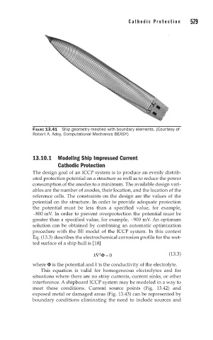
FIGURE 13.41 Ship geometry meshed with boundary elements. (Courtesy of
Robert A. Adey, Computational Mechanics BEASY)
13.10.1 Modeling Ship Impressed Current
Cathodic Protection
The design goal of an ICCP system is to produce an evenly distrib-
uted protection potential on a structure as well as to reduce the power
consumption of the anodes to a minimum. The available design vari-
ables are the number of anodes, their location, and the location of the
reference cells. The constraints on the design are the values of the
potential on the structure. In order to provide adequate protection
the potential must be less than a specified value, for example,
−800 mV. In order to prevent overprotection the potential must be
greater than a specified value, for example, −900 mV. An optimum
solution can be obtained by combining an automatic optimization
procedure with the BE model of the ICCP system. In this context
Eq. (13.3) describes the electrochemical corrosion profile for the wet-
ted surface of a ship hull is [18]
k∇ Φ = 0 (13.3)
2
where F is the potential and k is the conductivity of the electrolyte.
This equation is valid for homogeneous electrolytes and for
situations where there are no stray currents, current sinks, or other
interference. A shipboard ICCP system may be modeled in a way to
meet these conditions. Current source points (Fig. 13.42) and
exposed metal or damaged areas (Fig. 13.43) can be represented by
boundary conditions eliminating the need to include sources and