
Page 617 - Corrosion Engineering Principles and Practice
P. 617
580 C h a p t e r 1 3 C a t h o d i c P r o t e c t i o n 581
DC 1
DC 2
DC 3
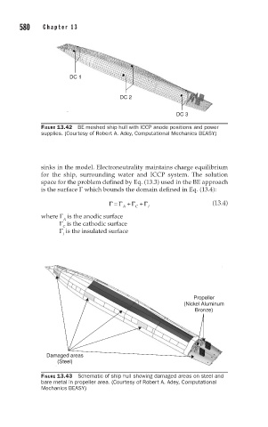
FIGURE 13.42 BE meshed ship hull with ICCP anode positions and power
supplies. (Courtesy of Robert A. Adey, Computational Mechanics BEASY)
sinks in the model. Electroneutrality maintains charge equilibrium
for the ship, surrounding water and ICCP system. The solution
space for the problem defined by Eq. (13.3) used in the BE approach
is the surface Γ which bounds the domain defined in Eq. (13.4):
Γ = Γ + Γ + Γ (13.4)
C
I
A
where Γ is the anodic surface
A
Γ is the cathodic surface
C
Γ is the insulated surface
I
Propeller
(Nickel Aluminum
Bronze)
Damaged areas
(Steel)
FIGURE 13.43 Schematic of ship hull showing damaged areas on steel and
bare metal in propeller area. (Courtesy of Robert A. Adey, Computational
Mechanics BEASY)