
Page 38 - Coulson Richardson's Chemical Engineering Vol.6 Chemical Engineering Design 4th Edition
P. 38
INTRODUCTION TO DESIGN
f 3 v 1 , v 3 , v 4 D 0
f 4 v 2 , v 4 , v 5 , v 6 D 0 21
f 5 v 5 , v 6 , v 7 D 0
There are seven variables, N v D 7, and five equations (relationships) N r D 5, so the
number of degrees of freedom is:
N d D N v N r D 7 5 D 2
The task is to select two variables from the total of seven in such a way as to give the
simplest, most efficient, method of solution to the seven equations. There are twenty-one
ways of selecting two items from seven.
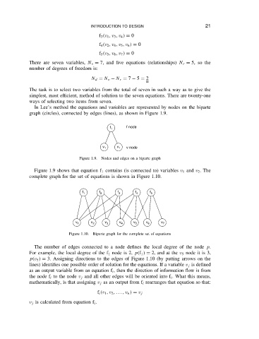
In Lee’s method the equations and variables are represented by nodes on the biparte
graph (circles), connected by edges (lines), as shown in Figure 1.9.
f 1 f node
v 1 v 1 v node
Figure 1.9. Nodes and edges on a biparte graph
Figure 1.9 shows that equation f 1 contains (is connected to) variables v 1 and v 2 .The
complete graph for the set of equations is shown in Figure 1.10.
f 1 f 2 f 3 f 4 f 5
v v v v v v v
1 2 3 4 5 6 7
Figure 1.10. Biparte graph for the complete set of equations
The number of edges connected to a node defines the local degree of the node p.
For example, the local degree of the f 1 node is 2, p f 1 D 2, and at the v 5 node it is 3,
p v 5 D 3. Assigning directions to the edges of Figure 1.10 (by putting arrows on the
lines) identifies one possible order of solution for the equations. If a variable v j is defined
as an output variable from an equation f i , then the direction of information flow is from
the node f i to the node v j and all other edges will be oriented into f i . What this means,
mathematically, is that assigning v j as an output from f i rearranges that equation so that:
f i v 1 , v 2 ,... , v n D v j
v j is calculated from equation f i .