
Page 112 - DSP Integrated Circuits
P. 112
3.17 FFT Processor—Case Study 1 97
3.17.1 Specification
The FFT is a commonly used benchmark for standard signal processors. We will
therefore study the implementation of an FFT processor that can compute a 1024-
point complex FFT with a throughput of more than 2000 FFTs per second. We set
the performance requirements slightly higher than what can be attained by one of
the best standard fixed-point 16-bit signal processors. The processor shall also be
able to perform both the FFT and the IFFT.
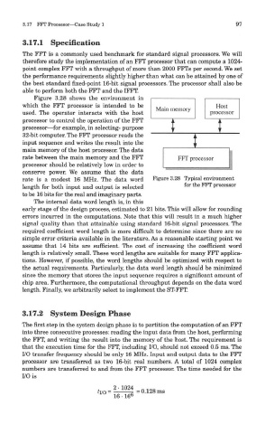
Figure 3.28 shows the environment in
which the FFT processor is intended to be
used. The operator interacts with the host
processor to control the operation of the FFT
processor—for example, in selecting- purpose
32-bit computer. The FFT processor reads the
input sequence and writes the result into the
main memory of the host processor. The data
rate between the main memory and the FFT
processor should be relatively low in order to
conserve power. We assume that the data
rate is a modest 16 MHz. The data word Figure 3.28 Typical environment
length for both input and output is selected for the FFT P rocessor
to be 16 bits for the real and imaginary parts.
The internal data word length is, in this
early stage of the design process, estimated to 21 bits. This will allow for rounding
errors incurred in the computations. Note that this will result in a much higher
signal quality than that attainable using standard 16-bit signal processors. The
required coefficient word length is more difficult to determine since there are no
simple error criteria available in the literature. As a reasonable starting point we
assume that 14 bits are sufficient. The cost of increasing the coefficient word
length is relatively small. These word lengths are suitable for many FFT applica-
tions. However, if possible, the word lengths should be optimized with respect to
the actual requirements. Particularly, the data word length should be minimized
since the memory that stores the input sequence requires a significant amount of
chip area. Furthermore, the computational throughput depends on the data word
length. Finally, we arbitrarily select to implement the ST-FFT.
3.17.2 System Design Phase
The first step in the system design phase is to partition the computation of an FFT
into three consecutive processes: reading the input data from the host, performing
the FFT, and writing the result into the memory of the host. The requirement is
that the execution time for the FFT, including I/O, should not exceed 0.5 ms. The
I/O transfer frequency should be only 16 MHz. Input and output data to the FFT
processor are transferred as two 16-bit real numbers. A total of 1024 complex
numbers are transferred to and from the FFT processor. The time needed for the
I/O is