
Page 224 - DSP Integrated Circuits
P. 224
5.6 Round-Off Noise 209
Generally, the output signal of a digital filter has a DC offset due to the aver-
age quantization error, as discussed already. A digital filter with M quantization
points has a DC offset of
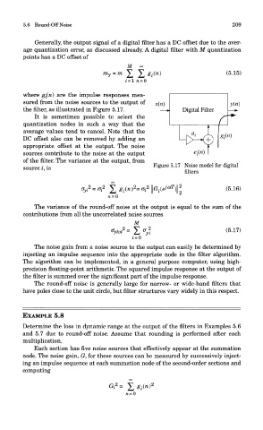
where gi(n) are the impulse responses mea-
sured from the noise sources to the output of
the filter, as illustrated in Figure 5.17.
It is sometimes possible to select the
quantization nodes in such a way that the
average values tend to cancel. Note that the
DC offset also can be removed by adding an
appropriate offset at the output. The noise
sources contribute to the noise at the output
of the filter. The variance at the output, from
source i, is Figure 5.17 Noise model for digital
filters
The variance of the round-off noise at the output is equal to the sum of the
contributions from all the uncorrelated noise sources
The noise gain from a noise source to the output can easily be determined by
injecting an impulse sequence into the appropriate node in the filter algorithm.
The algorithm can be implemented, in a general purpose computer, using high-
precision floating-point arithmetic. The squared impulse response at the output of
the filter is summed over the significant part of the impulse response.
The round-off noise is generally large for narrow- or wide-band filters that
have poles close to the unit circle, but filter structures vary widely in this respect.
EXAMPLE 5.8
Determine the loss in dynamic range at the output of the filters in Examples 5.6
and 5.7 due to round-off noise. Assume that rounding is performed after each
multiplication.
Each section has five noise sources that effectively appear at the summation
node. The noise gain, G, for these sources can be measured by successively inject-
ing an impulse sequence at each summation node of the second-order sections and
computing