
Page 159 - Decision Making Applications in Modern Power Systems
P. 159
Modeling and simulation Chapter | 5 123
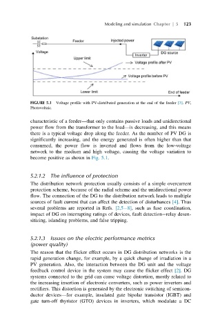
FIGURE 5.1 Voltage profile with PV-distributed generation at the end of the feeder [3]. PV,
Photovoltaic.
characteristic of a feeder—that only contains passive loads and unidirectional
power flow from the transformer to the load—is decreasing, and this means
there is a typical voltage drop along the feeder. As the number of PV DG is
significantly increasing, and the energy generated is often higher than that
consumed, the power flow is inverted and flows from the low-voltage
network to the medium and high voltage, causing the voltage variation to
become positive as shown in Fig. 5.1.
5.2.1.2 The influence of protection
The distribution network protection usually consists of a simple overcurrent
protection scheme, because of the radial scheme and the unidirectional power
flow. The connection of the DG to the distribution network leads to multiple
sources of fault current that can affect the detection of disturbances [4]. Thus
several problems are reported in Refs. [2,5 8], such as fuse coordination,
impact of DG on interrupting ratings of devices, fault detection relay desen-
sitizing, islanding problems, and false tripping.
5.2.1.3 Issues on the electric performance metrics
(power quality)
The reason that the flicker effect occurs in DG distribution networks is the
rapid generation change, for example, by a quick change of irradiation in a
PV generation. Also, the interaction between the DG unit and the voltage
feedback control device in the system may cause the flicker effect [2].DG
systems connected to the grid can cause voltage distortion, mostly related to
the increasing insertion of electronic converters, such as power inverters and
rectifiers. This distortion is generated by the electronic switching of semicon-
ductor devices—for example, insulated gate bipolar transistor (IGBT) and
gate turn-off thyristor (GTO) devices in inverters, which modulate a DC