
Page 435 - Decision Making Applications in Modern Power Systems
P. 435
Impact of demand-side management system Chapter | 15 395
PV plant CS-1 CS5
12 V DC bus
Array-1 Solar charge S1 LED-1
controller-1
Energy
S2 LED-2
storage
Module-1 S3 LED-3
S4 LED-4
Manual LED-5
Module-2 SD card control S5
Battery-1 TB-1
Timer
CS-3 reader circuit switches S6 TB-2
Module-3 (to log S7 Refrigerator
Battery-2 12 V DC bus data) S8
BB-1 S9 Washing
Module-4 Micro-controller
machine
(Arduino Mega)
Array-2
Battery-1
Module-1 S10 Pump
LCD
CS-4 Control room display S11 TB-3
Module-2 Battery-2 S12 TB-4
BB-2 S13 TB-5
S14 Fan-3
Module-3 Solar charge
controller-2 S15 Fan-2
S16 Fan-1
Module-4 CS-2 12 V DC bus
CS-6
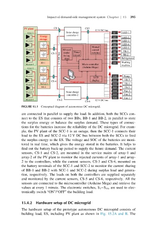
FIGURE 15.1 Conceptual diagram of autonomous DC microgrid.
are connected in parallel to supply the load. In addition, both the SCCs con-
nect to the ES that consists of two BBs, BB-1 and BB-2, in parallel to store
the surplus energy or balance the surplus demand. These types of connec-
tions for the batteries increase the reliability of the DC microgrid. For exam-
ple, the PV plant of the SCC-1 is an outage, then the SCC-1 connects their
load to the ES and SCC-2 via 12 V DC bus between both the SCCs to feed
the surplus energy to the ES. The voltage and SOC of the batteries are moni-
tored in real time, which gives the energy stored in the batteries. It helps to
find out the battery back-up period to supply the future demand. The current
sensors, CS-1 and CS-2, are mounted in the service mains of array-1 and
array-2 of the PV plant to monitor the injected currents of array-1 and array-
2 to the controllers, while the current sensors, CS-3 and CS-4, mounted on
the battery terminals of the SCC-1 and SCC-2 to monitor the current sharing
of BB-1 and BB-2 with SCC-1 and SCC-2 during surplus load and genera-
tion, respectively. The loads on both the controllers are supplied separately
and monitored by the current sensors, CS-5 and CS-6, respectively. All the
sensors are connected to the microcontroller (Arduino Mega) and retrieve the
values at every 1 minute. The electronic switches, S 1 S 16 , are used to elec-
tronically switch “ON”/“OFF” the building load.
15.4.2 Hardware setup of DC microgrid
The hardware setup of the prototype autonomous DC microgrid consists of
building load, ES, including PV plant as shown in Fig. 15.2A and B. The