
Page 43 - Defrosting for Air Source Heat Pump
P. 43
Previous related work: A review 33
on the surface of an outdoor coil will not necessarily be melted uniformly throughout
the surface. The frost over certain parts of the coil surface remains attached to the coil
surfaces until it is completely melted and sublimated while the frost over other parts
may be partially melted. It would then detach from the coil surface, falling down due
to gravity to the coil surfaces at lower levels or to a drainage tray. Two types of models
were developed, one system-based and the other the outdoor coil only.
2.4.2.1 Defrosting model system based
From the open literature available, modeling a defrosting process has attracted lots of
research attention. The early modeling work focused mainly on the outdoor coils of
simple geometry, such as finite slabs, a horizontal flat plate, or a flat-plate cooler.
Then, on a cylindrical coil cooler, a semiempirical model for electric defrosting
was presented, and an analytical model was developed to predict the evaporation, sub-
limation, and melting rates during defrosting. A moving boundary technique was used
and a defrosting process was divided into two stages, premelting and melting [12].
Later, Alebrahim and Sherif [107] reported an electric defrosting model for a
finned-tube outdoor coil using the enthalpy method to predict the defrosting duration
and frost surface temperature profiles. Thereafter, a number of studies on modeling a
defrosting process in ASHP units were carried out. Noticeably, an RCD model for an
outdoor coil was developed where the process of frost melting on the surface of an
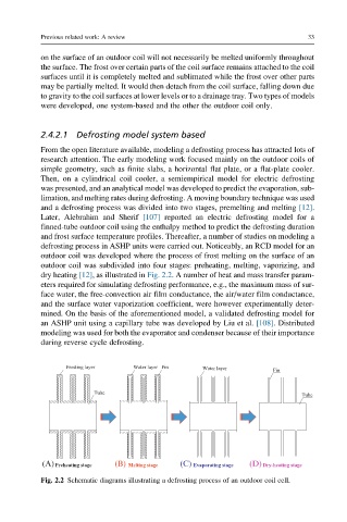
outdoor coil was subdivided into four stages: preheating, melting, vaporizing, and
dry heating [12], as illustrated in Fig. 2.2. A number of heat and mass transfer param-
eters required for simulating defrosting performance, e.g., the maximum mass of sur-
face water, the free-convection air film conductance, the air/water film conductance,
and the surface water vaporization coefficient, were however experimentally deter-
mined. On the basis of the aforementioned model, a validated defrosting model for
an ASHP unit using a capillary tube was developed by Liu et al. [108]. Distributed
modeling was used for both the evaporator and condenser because of their importance
during reverse cycle defrosting.
Fig. 2.2 Schematic diagrams illustrating a defrosting process of an outdoor coil cell.