
Page 208 - Design and Operation of Heat Exchangers and their Networks
P. 208
Optimal design of heat exchangers 197
which depends on the type of exchanger and the manufacturing tolerances
and is given as follows for some typical cases (Sinnott, 2005, Fig. 12.10):
Fixed and U tube : δ st ¼ 0:008 + 0:01d otl mðÞ (5.6)
Outside packed head : δ st ¼ 0:038 mðÞ (5.7)
Split ring floating head : δ st ¼ 0:0445 + 0:0276d otl mðÞ (5.8)
Pull through floating head : δ st ¼ 0:0858 + 0:0094d otl mðÞ (5.9)
The relationship between the tube bundle diameter and the number of
tubes for a standard tube layout can be expressed as
1=n
d otl ¼ N t =Kð Þ d o (5.10)
or
n
ð
N t ¼ Kd otl =d o Þ (5.11)
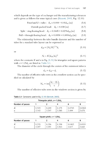
where the constants K and n in Eq. (5.10) for triangular and square patterns
with s¼1.25d o are listed in Table 5.1.
The diameter of the circle through the centers of the outermost tubes is
(5.12)
d ctl ¼ d otl d o
The number of effective tube rows in the crossflow section can be spec-
ified or calculated by
d s 2l c
N rc ¼ int (5.13)
s l
The number of effective tube rows in the windows section is given by
Table 5.1 Constants used in Eq. (5.10) (Sinnott, 2005).
Triangular pitch, s51.25d o
Number of passes 1 2 4 6 8
K 0.319 0.249 0.175 0.0743 0.0365
n 2.142 2.207 2.285 2.499 2.675
Square pitch, s51.25d o
Number of passes 1 2 4 6 8
K 0.215 0.156 0.158 0.0402 0.0331
n 2.207 2.291 2.263 2.617 2.643