
Page 33 - Design and Operation of Heat Exchangers and their Networks
P. 33
20 Design and operation of heat exchangers and their networks
10 3
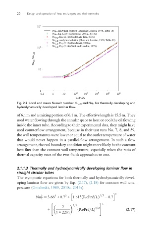
Nu H , analytical solution (Shah and London, 1978, Table 18)
Nu H , Eq. (2.15) (Gnielinski, 2010a, 2013a)
Nu exp , Eq. (2.16) (Sieder and Tate, 1936)
Nu x,H , analytical solution (Shah and London, 1978, Table 18)
Nu x,H , Eq. (2.13) (Gnielinski, 2010a)
10 2 Nu x,H , Eq. (2.14) (Shah and London, 1978)
Nu H , Nu x,H
10
1
0.1 1 10 10 2 10 3 10 4 10 5 10 6
RePrd/x
Fig. 2.2 Local and mean Nusselt number Nu x,H and Nu H for thermally developing and
hydrodynamically developed laminar flow.
of 6.1m and a mixing portion of 6.1m. The effective length is 15.5m. They
used water flowing through the annular space to heat or cool the oil flowing
inside the inner tube. According to their experimental data, they might have
used counterflow arrangement, because in their test runs No. 7, 8, and 39,
the wall temperatures were lower or equal to the outlet temperature of water
that would never happen in a parallel-flow arrangement. In such a flow
arrangement, the real boundary condition might more likely be the constant
heat flux than the constant wall temperature, especially when the ratio of
thermal capacity rates of the two fluids approaches to one.
2.1.1.3 Thermally and hydrodynamically developing laminar flow in
straight circular tubes
The asymptotic equations for both thermally and hydrodynamically devel-
oping laminar flow are given by Eqs. (2.17), (2.18) for constant wall tem-
perature (Gnielinski, 1989, 2010a, 2013a):
h i 3
3 3 3 1=3
Nu ¼ 3:66 +0:7 +1:615 RePrd=Lð Þ 0:7
T
" # 3
1=6
2 1=2
+ ð RePrd=LÞ (2.17)
1 + 22Pr