
Page 409 - Design and Operation of Heat Exchangers and their Networks
P. 409
392 Design and operation of heat exchangers and their networks
runs at a steady state, the heat load calculated with the data of the hot
fluidcan be expressedas
Q h ¼ _m h c p,h,m t t 00 (8.1)
0
h h
in which the specific isobaric thermal capacity c p,h,m is determined with the
mean temperature
t h,m ¼ t + t =2 (8.2)
00
0
h
h
Similarly, the heat load obtained from the cold fluid is
00
Q c ¼ _m c c p,c,m t t 0 (8.3)
c c
According to the energy balance,
Q h ¼ Q c + Q loss (8.4)
where Q loss is the heat loss to the environment. Because Q loss will be influ-
enced by many uncertain and unsteady effects, its value is difficult to esti-
mated and has large uncertainty. Therefore, the heat exchanger to be tested
shall be well thermally isolated so that the heat loss can be minimized and
neglected. Then, the heat duty of the heat exchanger can be determined by
Q ¼ Q h + Q c Þ=2 (8.5)
ð
An important parameter of the steady-state experiment is the energy bal-
ance error defined by
Q h Q c
ε ¼ 100% (8.6)
Q
Generally speaking, the energy balance error of a valid test run should
be <5%.
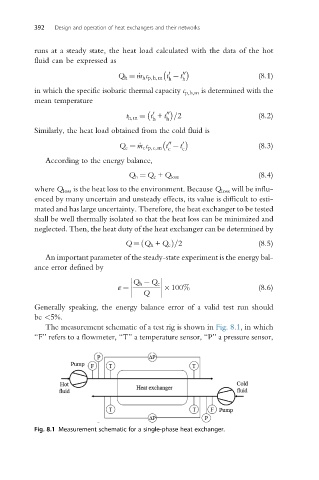
The measurement schematic of a test rig is shown in Fig. 8.1, in which
“F” refers to a flowmeter, “T” a temperature sensor, “P” a pressure sensor,
Fig. 8.1 Measurement schematic for a single-phase heat exchanger.